The invisible foundation
Network Infrastructure
A resilient, segmented wired and wireless foundation engineered for the traffic, privacy and uptime of a modern residence.
Design the coverage ↓Technology becomes experience
Beautiful outcomes begin with disciplined engineering.
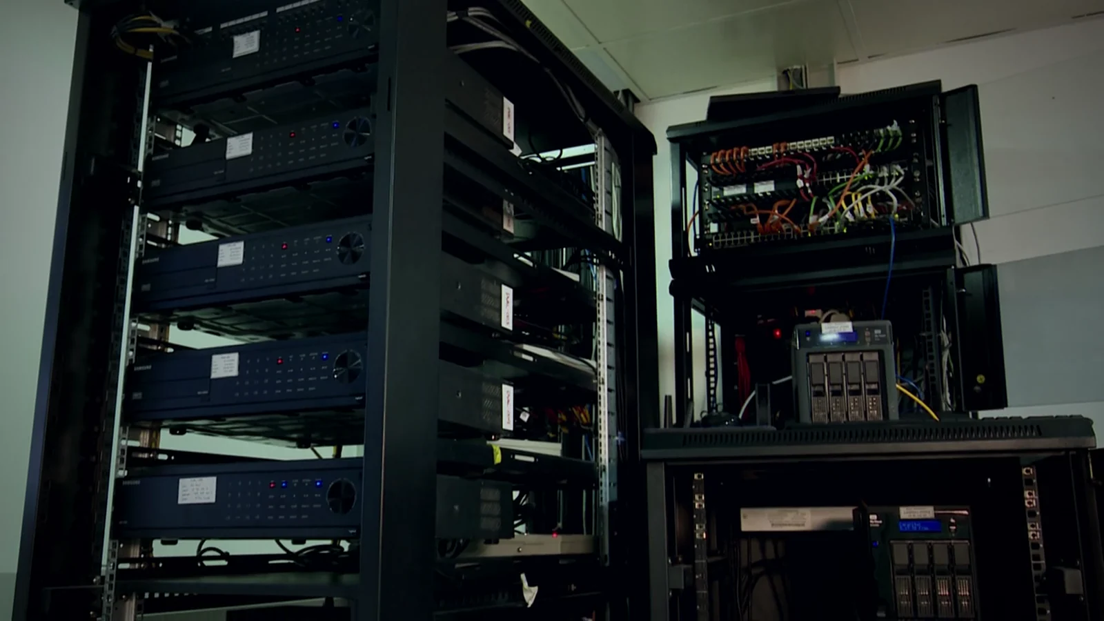
The complete the invisible foundation ecosystem
Managed Core
Documented switching, power and rack architecture.
The invisible path
Listen to the idea unfold in a calm, guided story.
Read the transcript
Most people notice the network only when it lets them down. A call stutters in the gallery. The terrace drops offline. Or a camera competes with movie night. We begin with the house itself—the floor plan, the steel, the stone, and the glass—and shape each radio cell around the way signal actually travels. Move an access point here, and you may improve one room while crowding the next. So we measure. We tune power and channels. And we walk the residence with real devices. The result feels wonderfully ordinary. Your phone simply finds the better connection, room after room, without asking you to think about it.
Ready to play
Coverage is shaped, not guessed
Place the access point.
Watch the home change.
Add or move an access point, change bands and compare cell design. Your phone makes the final roaming decision; the engineered network makes the better connection unmistakably better.
Whole-home overview
See signal become part of the architecture.
Walk the home · reveal the materials · balance the coverageThe architecture is part of the antenna system
Walls reshape the signal.
Structure and mechanical assemblies can reflect RF and isolate an entire side of a floor.
The visual shows potentially severe reflection; the finished assembly must be measured.
Fine-tune each interface
One access point.
Three very different radios.
Select an access point above to see how each interface can be tuned for a distinct job.
radio0 · 2.4 GHzCh 6 · 20 MHz · 7 dBm
Low-rate and compatibility devices
radio1 · 5 GHzCh 149 · 40 MHz
Primary phones, tablets and laptops
radio2 · 6 GHzSite validated
Capable clients after site validation
Measure habits · protect the bottleneck
Test the home the way the family actually uses it.
Purpose-built scripts sample controller and gateway telemetry plus synthetic traffic—not personal content. They reveal retries, utilization, latency, jitter and roaming gaps during the moments that matter.
every("15s", collect([
  "RSSI", "SNR", "retries", "channelUse"
]));

flagWhen("RSSI", "< -67 dBm");
flagWhen("SNR", "< 25 dB");
flagWhen("channelUse", "> 50%");

prioritize("interactive-call");
schedule("bulk-backup", "02:00–06:00");
verify("control", "video", "roaming");- ProtectionSecurityDedicated monitoring, entry and life-safety planned as one calm response.
- AwarenessSurveillanceUseful camera events, secure recording and coordinated property response.
- AtmosphereLightingArchitectural light, precise dimming and scenes tuned to each room.
- DaylightShadesQuiet automated privacy, glare control and a considered fabric palette.
- MusicAudioSynchronized music and engineered listening without visual clutter.
- CinemaVideoDistributed sources and immersive rooms designed around the experience.
A private design conversation